Processes
Workflow | Processes
Workflow processes are needed to enable work processes to be performed in a structured manner. A workflow process is divided into individual process steps in which various employees or teams take part.
The processes in eserp can also be used without the automated processes in order to visualize or document the processes in a company using the BPMN standard.
An already defined workflow process can be incorporated as a sub process into a further process, so that already created processes can be re-used multiple times.
When planning a workflow process, remember that a target event is required as well as the start event. During execution of the individual process steps always remember that the process will also reach the end regardless of the individual events, gateways, and tasks. Logical errors in the planning are not checked by the program during creation.
'Details' tab
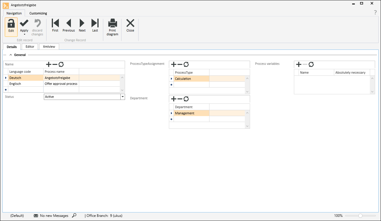
You can record further information and process assignments for a workflow process on the Details tab.
Name
Assign a unique name to the workflow process. This name will appear in the Process selection.
Status
Select the status that the process is to have here. Among other things, the process status controls its visibility and execution.
Active
The workflow process is active and can be started either manually or by a condition.
Inactive
The process is not available for execution and is not displayed in the list of processes available for selection.
Draft
A newly created process is given Draft status. This status means that the process is not available for selection and also cannot be started.
Process type / Assignment
The process types for which the workflow process can be executed is specified here.
For example, if you want to use an Offer calculation within a process, select the process type Calculation,
Click on the ![]() button above the Process type table to add another process type. Click on the
button above the Process type table to add another process type. Click on the ![]() button in the particular row of the table to select the process type.
button in the particular row of the table to select the process type.
Department
Select one or more Departments here that the workflow process is to be available to. The selection of available processes can be restricted using a filter.
Click on the ![]() button above the Departments table to add another Department. Click on the
button above the Departments table to add another Department. Click on the ![]() button in the particular row of the table to select the process type.
button in the particular row of the table to select the process type.
Process variables
Process variables can be defined here for the use of scripts for Business Rule Tasks and Script Tasks within the workflow. Process variables can also be used transfer results to a sub process.
Name
Assign a unique name for the process variable. Avoid the use of special characters and modified characters in the name.
Absolutely necessary
Activate this option if the process variable is absolutely necessary for execution of the process.
'Editor' tab
The workflow process with its individual process steps is defined in the Process editor.
The process design is based on the BPMN 2.0 standard (Business Process Model and Notation).
When you select the Editor tab, there are four toolbars available for the process design and functions:
-
Navigation
-
Customizing
-
Editor
-
Icons
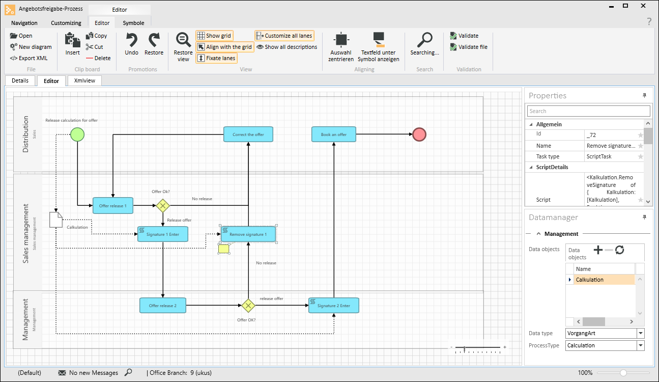
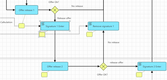
Process editor
Workflow processes can be designed graphically in the Editor window. Various tools and BPMN icons are provided in the toolbar for this.
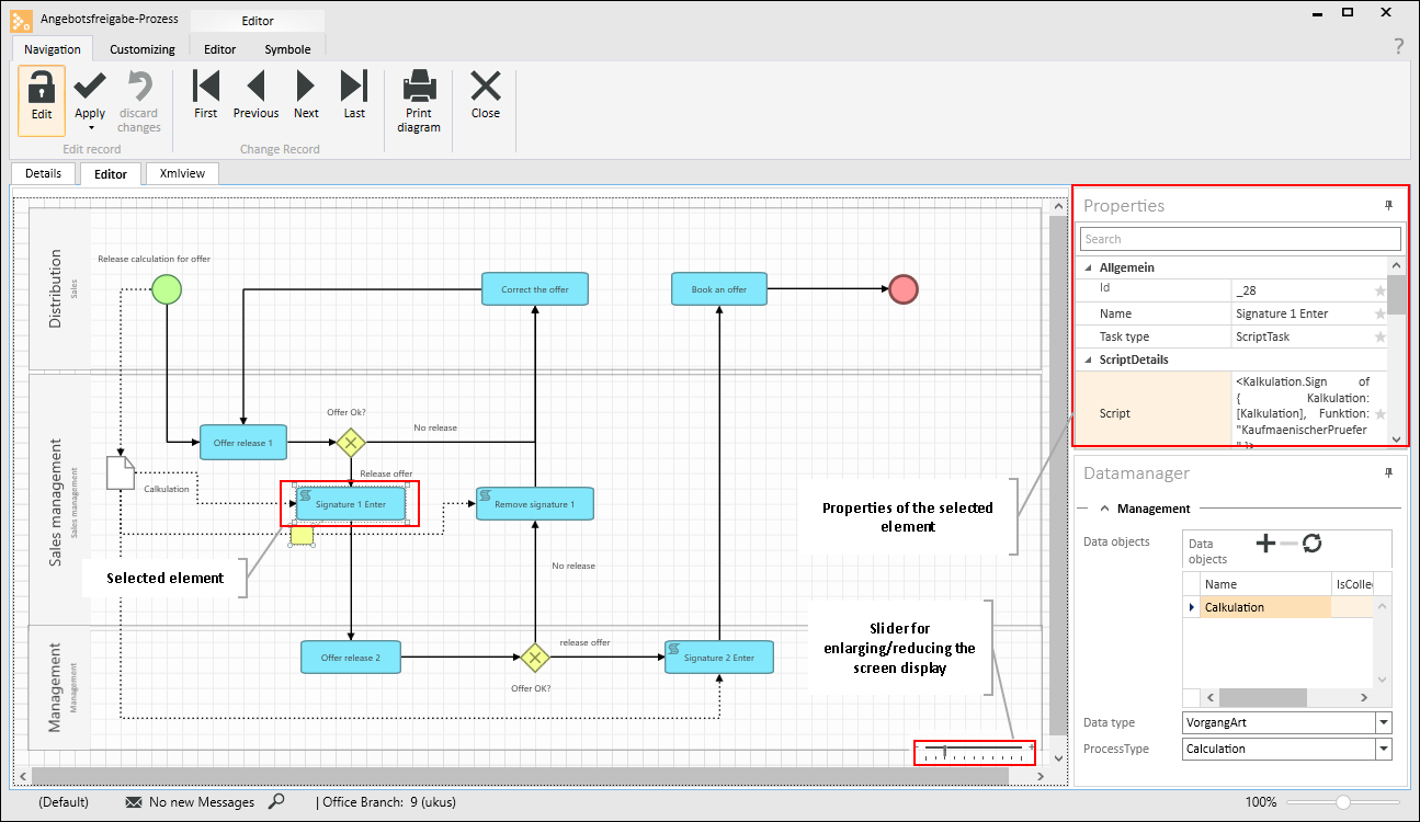
Settings can be assigned to each BPMN element / icon. To do this, click on an Element. The available properties will be shown in the Settings dialog. Different properties will be available depending on the Element selected, and further options can be shown when a Property (e.g. Task type or Event type) is edited.
The Settings dialog can be docked onto any part of the program window (also see Docking).
Customize display
The display can be enlarged or reduced by using the slider at bottom right of the Editor window.
Highlight elements
Individual elements are highlighted with a mouse click. A highlighted element can be moved by dragging it with the mouse (hold down left mouse button).
To highlight all the elements in the Editor window, press CTRL + A.
To highlight several elements in the Editor window, press and hold down the CTRL key and left click on the individual elements.
You can also select several elements by holding down the left mouse button.
Modify element size
Left click on the element to highlight it. Four squares appear at the element corners. Drag one of these squares with the left mouse button pressed to change the size of the icon. Circles at the corners of an element indicate that it can be moved but not enlarged.
Link elements
To link one element to another element, highlight the starting element. Hold the mouse pointer over the element. Four links (circles) will be displayed. Hold down the left mouse button and drag one of these links on to the link of another element.
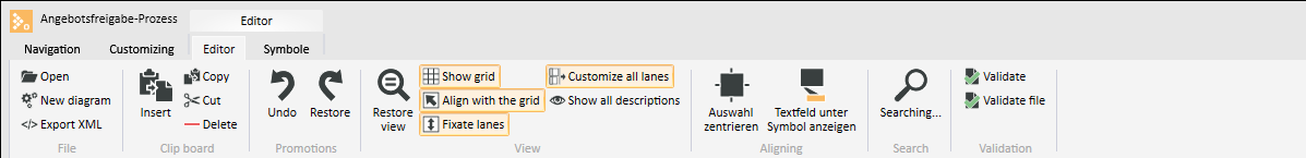
'Editor' toolbar
The Editor toolbar provides functions for designing the graphical process.
|
Icon |
Meaning |
Explanation |
|---|---|---|
|
|
Open |
Opens an XML or BPMN format diagram file. After the file is selected, it is validated to ensure that it matches the desired format. |
|
|
New diagram |
Opens a further Editor window for a new workflow process / diagram. |
|
|
Export XML |
Exports the current workflow process in XML format, including Script Tasks and Business Rule Tasks. The file is saved as a compressed ZIP archive. |
|
|
Clip board Insert |
Inserts the elements previously cut or copied to the clip board into the Editor window. |
|
|
Clip board Copy |
Copies the selected elements to the clip board, the highlighted elements are retained. |
|
|
Clip board Cut |
Places the selected elements on the clip board and deletes them. |
|
|
Delete |
Deletes the selected elements. Highlighted elements can also be deleted by pressing the <DEL> key. |
|
|
Undo |
Undoes the last action (e.g. move element, delete, etc.). |
|
|
Restore |
Redoes the last action that was undone. |
|
|
Restore view |
The display can be enlarged or reduced by using the slider at bottom right of the Editor window. This function resets the view (slider set to the mid point). |
|
|
Show grid |
Displays a grid on the screen to enable better alignment of elements. The Snap to grid function aligns the elements with this grid. |
|
|
Snap to grid |
The elements can be aligned to the grid when they are positioned. The grid is displayed using the Show grid function. |
|
|
Fix lanes |
Fixes the swimming lanes to the left hand edge. The swimming lanes can still be shifted up or down. |
|
|
Customize all lanes |
If this function is activated, all the highlighted swimming lanes will be changed at the same time when you alter the width of one. |
|
|
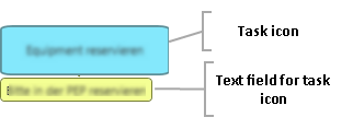
Show all descriptions |
If this option is activated, the available descriptions will be displayed for all Task elements. These descriptions will be shown as yellow text fields near the icons (not available for all elements).
Additional notes can be entered in the text field, which will be displayed when the workflow process is executed. |
|
|
Center selection |
Centers the selected elements. |
|
|
Show text field below icon |
Text fields (yellow icons) can be moved to any position. This function restores them to the position directly below the highlighted icon.
Additional notes can be entered in the text field, which will be displayed when the workflow process is executed. Double click in a text field to enter text.
|
|
|
Search |
You can search for a search term in all elements. All the elements that contain the search term will be highlighted. |
|
|
Validate |
Checks the workflow process for errors. Possible errors are displayed below the Editor window. Possible errors are missing start or end events or missing sequence flows. Logical errors in planning are not checked. |
|
|
Validate file |
Checks if an XML or BPMN format file can be processed. This allows you to check that a file matches the XML or BPMN 2.0 format before it is imported from another application. |
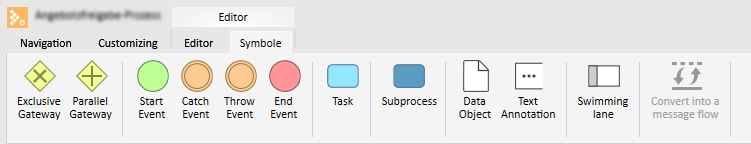
'Icons' toolbar
The available BPMN elements are described in the following table. The usual English label for each element is shown in the Meaning column.
Insert elements
To insert an element from the toolbar into the Editor window, hold down the left mouse button and drag the element to an empty space on the workspace. When you release the mouse button, the element will be inserted at the position under the mouse pointer.
Please note that not all of the standard BPMN elements are available. Only the elements that allow automatic processing in eserp are available.
|
BPMN icon |
Meaning |
Explanation |
|---|---|---|
|
|
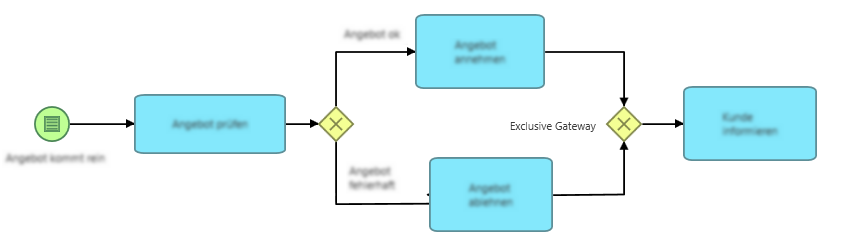
Exclusive Gateway (-)
|
Exclusive gateway based on data (either OR). Only one path is traversed, which path is decided by a user action within a task.
|
|
|
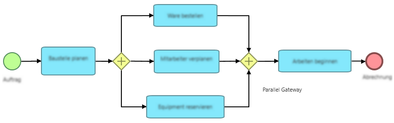
Parallel Gateway (-) |
Parallel gateway (AND) All paths are traversed.
|
|
|
Start Event (start event) |
At least one start event is absolutely essential for the creation of a workflow process. The start for this event is triggered manually by selecting the process in the particular process. The start event can also be assigned an event type in the Settings settings. At present the No event (default) and Condition event types are supported. The appearance of the icon changes depending on the selected event type (see description below). |
|
|
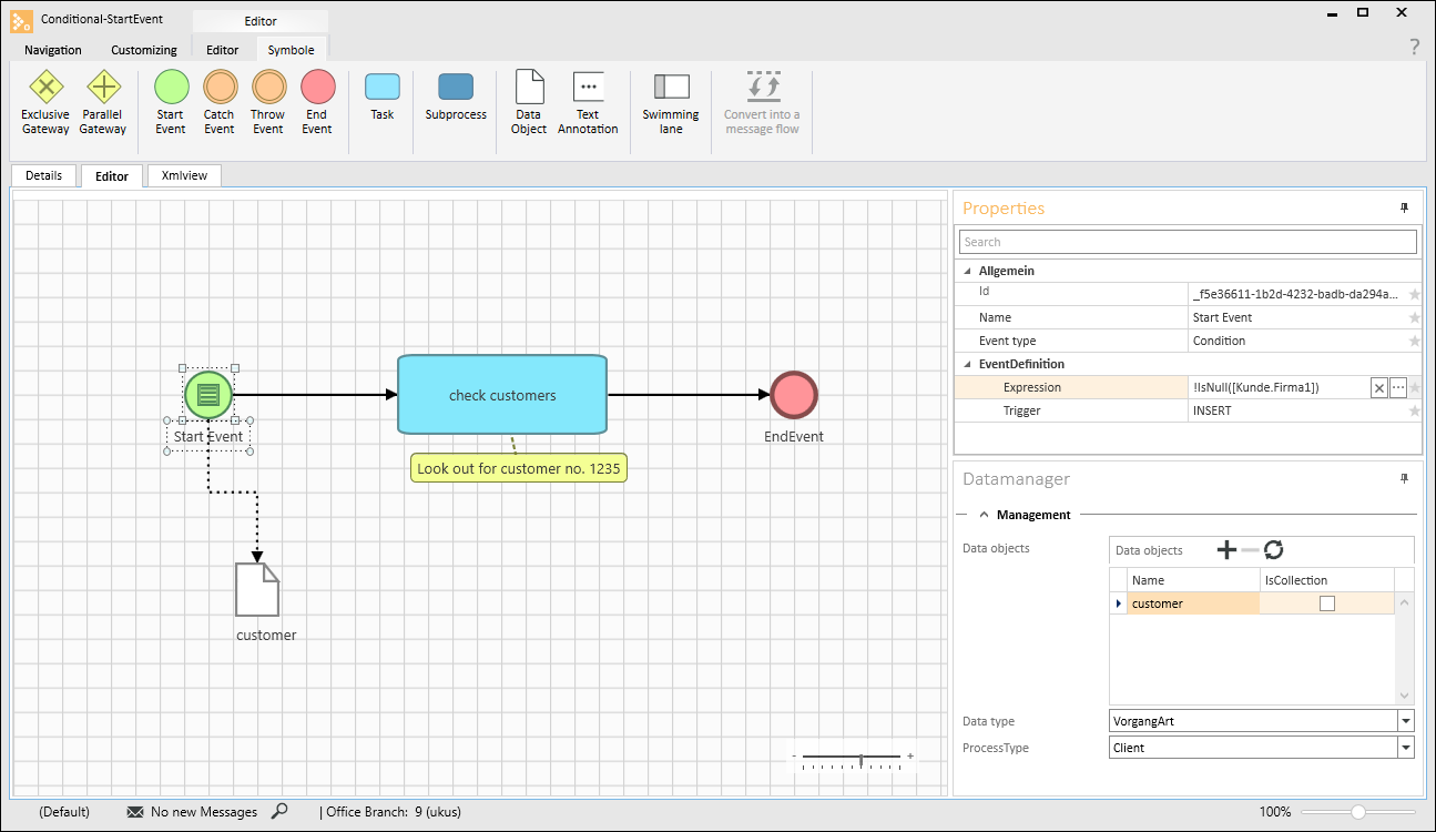
Start Event Condition (-) |
Start event with condition event type; the start is controlled by the event (condition). A data object must be assigned for a condition controlled start event. The process start can be linked to a database condition and an expression (Expression -> Database functions, Operands, Database fields and Constants) e.g. when a data set in a table is created, edited or meets a condition. You can then select whether the start event is triggered by INSERT, or UPDATE, or INSERT AND UPDATE.
For example, if you specify INSERT as the trigger, the specified expression will be checked for this start event when you insert a new project order. The expression could then for example contain: [DataObject.OrderNo] > 0; Since this condition is automatically TRUE when a new Project order is created, this workflow will always start automatically.
Alternatively, an update could be used to check a certain status. For example, if the project manager sets the order to Approved for costing, a task is automatically generated for the costing team. |
|
|
Catch Event |
Intermediate result Has no effect on the process sequence |
|
|
Throw Event |
Intermediate result Has no effect on the process sequence |
|
|
End Event (-) |
The end event is absolutely necessary for creation of a workflow process. |
|
|
Standard Task (-) |
A task describes an individual process step or a work unit. Various types of process step are available; a Task type can be selected in the Settings settings. The following task types are supported:
Other task types (Send Task, Receive Task and Service Task) can be selected but these currently provide only the functions of a Standard Task. Different properties can be selected depending on the Task type selection. The appearance of the Task icon also changes (also see description below). |
|
|
Manual Task (-) |
Task type Manual Task A manual process step without IT support is performed. |
|
|
User Task (-) |
Task type User Task A user process step is performed by a user with IT support. |
|
|
Business Rule Task (-) |
Task type Business Rule Task A business rule is evaluated for this type of process step. The business rule can be used to start the process step or control the further processing of process steps. Business rules are created using the es Expression Language (ESEL) script language. Also see Business rules |
|
|
Script Task (-) |
Task type Script Task This type of process step does not require any user action. A script is automatically run within the process step, e.g. to insert a signature in a calculation folder. |
|
|
Subprocess (-) |
A branch to a sub process takes place in this process step. The sub process is a process that can be activated by different processes. Defined process variables can be handed over to a sub process. |
|
|
Data Object (-) |
Process specific data are stored in a data object, e.g. Calculation data or Client data. Process types and document types can be specified. Data objects indicate the data that flows from one object to the next. A data object is required for the description of event controlled start events so that the start condition can be created. A maximum of one data object can be linked to a start event. The data recorded in a data object are available within the workflow process. |
|
|
Text Annotation (-) |
Text annotations allow you to record notes and additional information. They have no meaning for process execution. |
|
|
Swimming lane (-) |
The elements placed within a lane belong to a Responsibility. The responsibilities can be Teams, Address roles, or placeholders for process variables (Teams and Address roles). |
|
|
Convert into a message flow Convert into sequential flow
|
Depending on the type of link selected:
|

Data manager
If data objects are used within the process, you can manage the data links using the Data Manager button in the Process editor. The Data Manager window can be docked on to any point in the program window, e.g. on the right hand side together with the Object properties.
Data objects
Data objects can be assigned in this table.
Please note that only the Data Objects that are visible in the Editor will be considered in the process steps.
You can create as many data links as you like in the Data Manager, and only associated links can also be used.
Name
Assign a name to the data link.
Is Collection
This option is set automatically if the data is a collection of data. Not currently supported.
Data type
You can select here between Process type and Document type. Depending on your selection, this field will be labeled Process type or Document type and the corresponding selections will be shown.
Process type / Document type
Depending on what you have selected in the data type field, you will have the choice here between process types or document types.
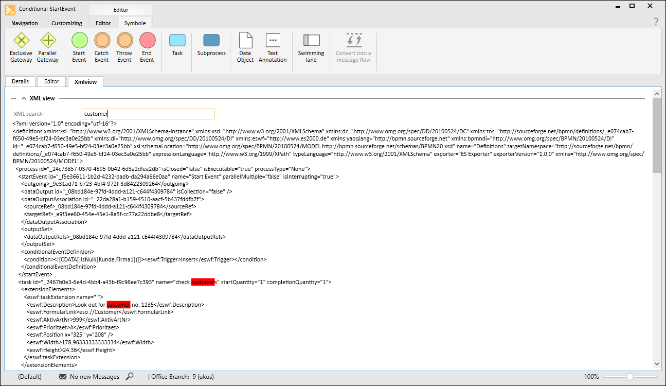
XML view tab
The process shown graphically on the Editor tab is shown in XML format on this tab. You cannot edit the XML source text. It is merely displayed here for information.
You can search for words / values within the file using the XML search field.